RECOMMEND STANDARD SERIES 50
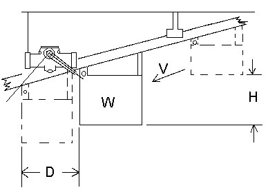
The examples of shock absorber mounting shown illustrate a typical application that can be used to aid in sizing the shock absorber unit to a system. It is recommended that the system should be designed at 60% of the units rated capacity. This allows the best adjustment control (mid-range of adjustment). CAUTION: Exceeding the published maximum energy, angle of travel or using either end of the unit’s travel as a positive stop for the system VOIDS the warranty of the unit.
SYMBOLS
E = Energy Inch Pounds
W = Weight Pounds
V = Contact Velocity Ft/Sec.
Note: Contact Engineering Department is contact velocity exceeds 30 ft./sec.
H = Total Vertical Distance Inches
T = Deceleration Time Sec
D = Shock Absorber Stroke Inches
G = Deceleration Force Pounds
F = Driving Force Pounds
T = Propelling Torque Inch Pounds
Ø= Deceleration Angle Radians
Note: 1 Radian = 57.3 Degrees
